Topology
- Inter VLAN Routing is used to make the devices in different VLANs to communicate with each other. Here we are configuring inter VLAN routing using an L2 switch and a router. In a scenario where an L3 switch is being used, we can straight away configure routing without a router.
Switch(config-vlan)#name test01
Switch(config)#vlan 20
Switch(config-vlan)#name test02
Assign the switch ports connected to the PCs to the respective VLANs
Switch(config)#int fas0/1
Switch(config-if)#switchport mode access
Switch(config-if)#switchport access vlan 10
Switch(config)#interface fas0/2
Switch(config-if)#switchport mode access
Switch(config-if)#switchport access vlan 20
Configure the port connecting to the router as trunk and allow the two VLANs
Switch(config)#int fas0/3
Switch(config-if)#switchport mode trunk
Switch(config-if)#switchport trunk allowed vlan add 10
Switch(config-if)#switchport trunk allowed vlan add 20
Create two sub-interfaces on router for the two VLANs and configure the Gateway IP addresses.
For Vlan 10
fa0/1.10
IP:192.168.10.10/24
Router(config)#int fas0/1
Router(config-if)#no shutdown
Router(config)#int fas0/1.10
Router(config-subif)#encapsulation dot1Q 10 (10 in this commands is the VLAN id 10)
Router(config-subif)#ip address 192.168.10.10 255.255.255.0
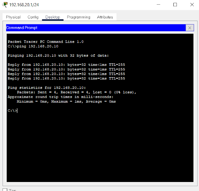
For Vlan 20
fa0/1.20
IP:192.168.20.10/24
Router(config)#int fas0/1.20
Router(config-subif)#encapsulation dot1Q 20


.png)


0 Comments